Matter MCXW71 Lighting Example Application#
For generic information related to on/off light application, please see the common README.
Introduction#
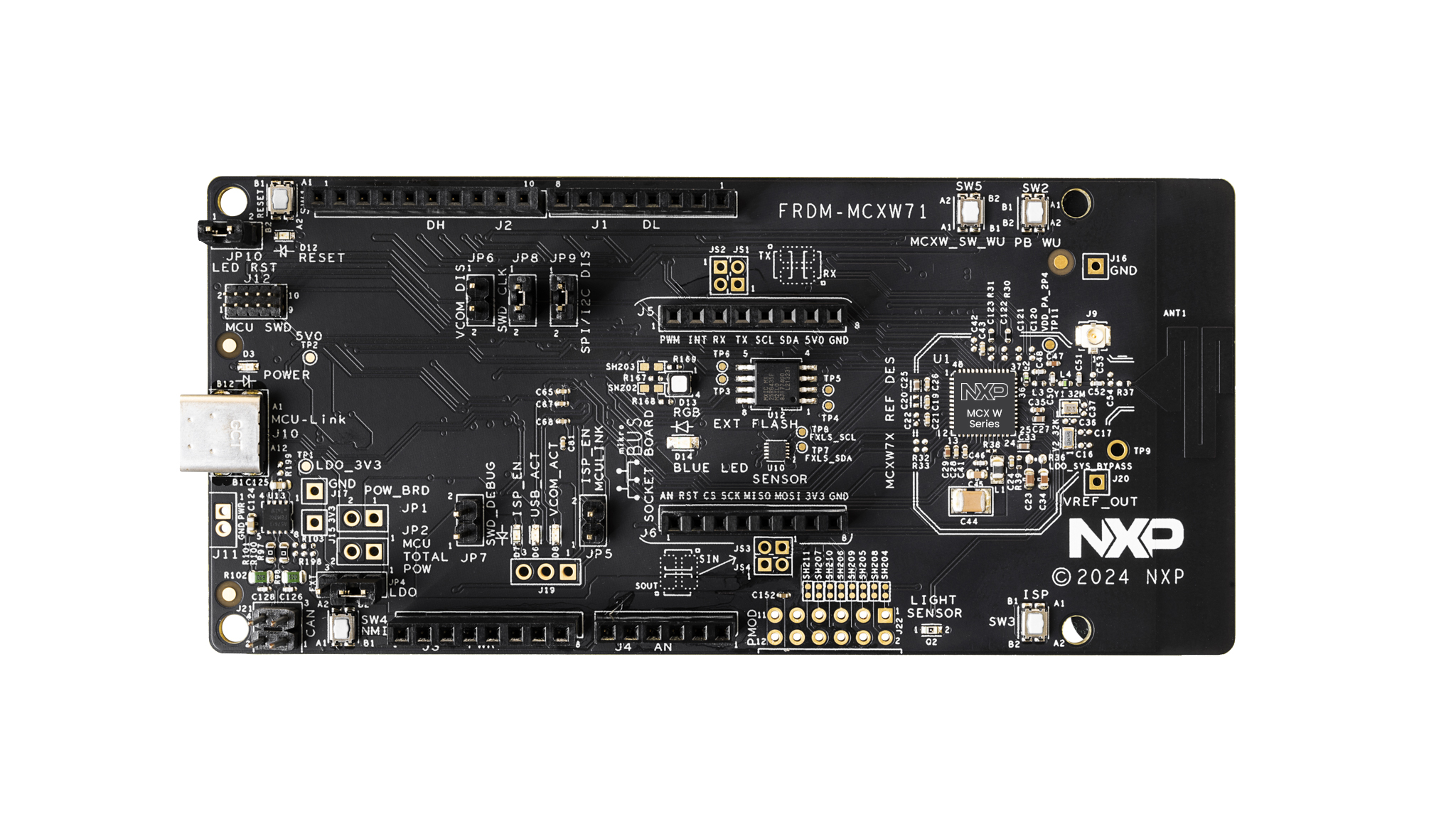
This is an on/off lighting application implemented for an mcxw71 device.
The following board was used when testing this Matter reference app for a
mcxw71 device:
Device UI#
The state feedback is provided through LED effects:
widget |
effect |
description |
|---|---|---|
LED2 |
short flash on (50ms on/950ms off) |
The device is in an unprovisioned (unpaired) state and is waiting for a commissioner to connect. |
LED2 |
rapid even flashing (100ms period) |
The device is in an unprovisioned state and a commissioner is connected via BLE. |
LED2 |
short flash off (950ms on/50ms off) |
The device is fully provisioned, but does not yet have full network (Thread) or service connectivity. |
LED2 |
solid on |
The device is fully provisioned and has full network and service connectivity. |
RGB LED |
on |
The |
RGB LED |
off |
The |
NOTE: LED2 will be disabled when OTA is used. On FRDM-MCXW71 board, PTB0
is wired to both LED2 and CS (Chip Select) of the External Flash Memory. Since
the OTA image is stored in external memory, LED2 operations will affect OTA
operation by corrupting packages and OTA will not work.
The user actions are summarized below:
button |
action |
output |
|---|---|---|
SW2 |
short press |
Enable BLE advertising |
SW2 |
long press |
Initiate a factory reset (can be cancelled by pressing the button again within the factory reset timeout limit - 6 seconds by default) |
SW3 |
short press |
Toggle attribute |
SW3 |
long press |
Clean soft reset of the device (takes into account proper Matter shutdown procedure) |
The example application provides a simple UI that depicts the state of the
device and offers basic user control. This UI is implemented via the
general-purpose LEDs and buttons built in the MCXW71 board.
Building#
Manually building requires running the following commands:
user@ubuntu:~/Desktop/git/connectedhomeip$ cd examples/lighting-app/nxp/mcxw71
user@ubuntu:~/Desktop/git/connectedhomeip/examples/lighting-app/nxp/mcxw71$ gn gen out/debug
user@ubuntu:~/Desktop/git/connectedhomeip/examples/lighting-app/nxp/mcxw71$ ninja -C out/debug
Please note that running gn gen out/debug without --args option will use the
default gn args values found in args.gni.
After a successful build, the elf and srec files are found in out/debug/.
See the files prefixed with chip-mcxw71-light-example.
SMU2 Memory#
Additional memory is provided to the application by moving some Matter instances
and global variables in the shared memory area from NBU domain.
Note: These instances and global variables are placed in SMU2 memory through
name matching in the application linker script. They should not be changed or,
if changed, the names must be updated in app.ld. See
app.ld for names and SMU2
memory range size.
When compiling the application as an OT Full Thread Device
(chip_openthread_ftd=true), using nxp_use_smu2_static=true gn arg will cause
the following symbols to be moved to SMU2 area:
symbol name |
file |
|---|---|
|
|
|
|
|
|
|
|
Additionally, using nxp_use_smu2_dynamic=true will cause the OpenThread
buffers to be dynamically allocated from a 13KB SMU2 range after a successful
commissioning process.
nxp_use_smu2_static and nxp_use_smu2_dynamic are set to true in the
default example.
LED PWM#
In the default configuration, the onboard RGB LED pins are configured as GPIO
pins. In order to enable the dimming feature, the pins need to be configured in
PWM mode and synced with channels of the TPM (Timer PWM Module). To enable
this feature, compile the application with: nxp_config_dimmable_led=true
If the feature is enabled, the LED brightness can be controlled using
LevelControl cluster
commands.
Flashing#
Two images must be written to the board: one for the host (CM33) and one for the
NBU (CM3).
The image needed on the host side is the one generated in out/debug/ while the
one needed on the NBU side can be found in the downloaded NXP-SDK package at
path -
middleware\wireless\ieee-802.15.4\bin\k32w1_mcxw71\k32w1_mcxw71_nbu_ble_15_4_dyn_matter.sb3.
Flashing the NBU image#
NBU image should be written only when a new NXP SDK is released.
Install Secure Provisioning SDK tool using Python:
pip install spsdk
Note: There might be some dependencies that cause conflicts with already installed Python modules. However,
blhosttool is still installed and can be used.Updating
NBUfor Wireless examplesIt is necessary to work with the matching
NBUimage for the SDK version of the application you are working with. This means that when you download your SDK, prior to loading any wireless SDK example, update yourNBUimage with the SDK provided binaries. ForFRDMusers, please write the following binary:middleware\wireless\ieee-802.15.4\bin\mcxw71\mcxw71_nbu_ble_15_4_dyn_matter_<nbu_version>.sb3Please note that
<nbu_version>may vary depending on the SDK version.Place your device in
ISPmode.Make sure a jumper is placed on
JP25Press and hold
SW4, press and release Reset, then releaseSW4
Once the device is connected, you may find the assigned port by running:
nxpdevscanRun the
blhostcommand to write thesb3file:blhost -p <assigned_port> receive-sb-file <path_to_SDK>\middleware\wireless\ieee-802.15.4\bin\mcxw71\mcxw71_nbu_ble_15_4_dyn_matter_<nbu_version>.sb3
Flashing the host image#
Host image is the one found under out/debug/. It should be written after each
build process.
If debugging is needed then jump directly to the Debugging section. Otherwise, if only flashing is needed then JLink can be used:
Plug
MCXW71to the USB port (no need to keep theSW4button pressed while doing this, e.g. ISP mode is not needed for host flashing)Connect JLink to the device:
JLinkExe -device MCXW71 -if SWD -speed 4000 -autoconnect 1
Run the following commands:
reset
halt
loadfile chip-mcxw71-light-example.srec
reset
go
quit
Debugging#
One option for debugging would be to use MCUXpresso IDE.
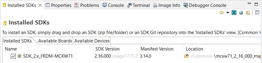
Drag-and-drop the zip file containing the NXP SDK in the “Installed SDKs” tab:
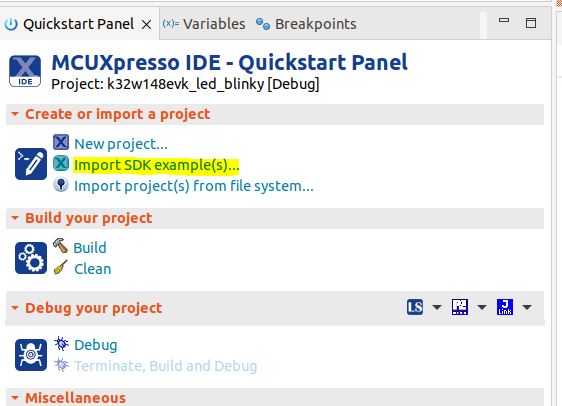
Import any demo application from the installed SDK:
Import SDK example(s).. -> choose a demo app (demo_apps -> hello_world) -> Finish
Flash the previously imported demo application on the board:
Right click on the application (from Project Explorer) -> Debug as -> JLink/CMSIS-DAP
After this step, a debug configuration specific for the MCXW71 board was
created. This debug configuration will be used later on for debugging the
application resulted after ot-nxp compilation.
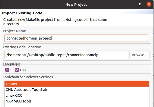
Import Matter repo in MCUXpresso IDE as Makefile Project. Use none as Toolchain for Indexer Settings:
File -> Import -> C/C++ -> Existing Code as Makefile Project
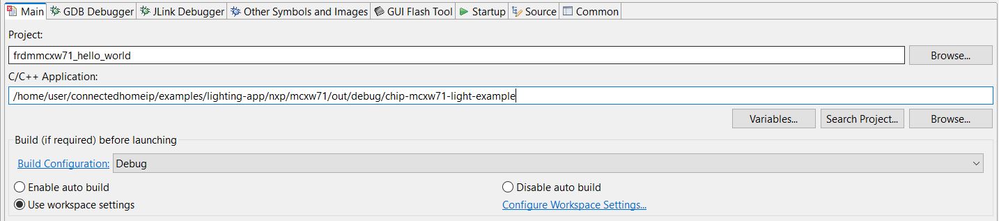
Replace the path of the existing demo application with the path of the
MCXW71application:
Run -> Debug Configurations... -> C/C++ Application
Running RPC console#
To build example with RPC enabled, use the following gn command:
gn gen out/debug --args='import("//with_pw_rpc.gni") treat_warnings_as_errors=false'
The application runs an RPC server and processes events coming from an RPC
client. An example of an RPC client is the chip-console, which can be accessed
by running:
chip-console --device /dev/tty.<SERIALDEVICE> -b 115200 -o pw_log.out
The console should have already been installed in the virtual environment. From
the chip-console, a user can send specific commands to the device.
For button commands, please run rpcs.chip.rpc.Button.Event(index) based on the
table below:
index |
action |
|---|---|
0 |
Start/stop BLE advertising |
1 |
Factory reset the device |
2 |
Application specific action (e.g. toggle LED) |
3 |
Soft reset the device |
To reboot the device, please run rpcs.chip.rpc.Device.Reboot().
OTA#
Please see mcxw71 OTA guide.